
INSTRUCTIONS
L5P DURAMAX DOWNPIPE AND EGR
INSTRUCTIONS
2017-19 L5P Duramax 3 1⁄2” Down Pipe & EGR Fix Kit
1. First, locate the packing list included with the kit and double check you have all items on the list.
2. Disconnect the negative battery cables from both batteries.
3. Remove the passenger side inner fender liner.
4. Drain the Engine coolant from the passenger side lower corner of the radiator by removing the plastic threaded plug. (NOTE: The coolant tank cap is reverse thread, BUT we recommend not removing the cap right away otherwise coolant will blast out from the drain plug all over the front suspension. Leave the tank cap on, and let the coolant drain out slowly into the bucket, much less mess this way.)
5. Remove the intake pipe & Intake air box.
6. If you are having trouble at this point during the disassembly process without pictures in the instructions, we strongly recommend that you do not continue, and you contact a certified Diesel Performance shop to install these components.
7. Next remove the heat shield on the EGR hot side pipe circled below that connects the EGR valve to the Cooler and to the Y-bridge. Then remove the six 13mm head bolts holding the pipe on.

8. Next remove the turbo intake horn and PCV hose. The PCV Hose has a non-removable metal band on it, loosen/spin clamp with a hood tool or flat blade screw driver first and then with pulling force and a flat blade screw driver or pry bar pushing on the bottom of the hose, the hose will disconnect from the horn with the metal band remaining in place. Leave the PCV hose connected to the PCV box on the driver side upper valve cover.
9. Two bolts connect the horn to the turbocharger; you will need to use a 13mm SWIVEL SOCKET 1⁄4” drive and long extension to remove these bolts. If you drop them not a big deal they will be easy to access soon.

10. Remove the small diameter aluminum coolant line assembly that is bolted to the top of the Y-bridge. Leave all connecting hoses in place, just remove the aluminum hardline assembly only at this point.

11. Next, remove the 13mm head bolt on the plastic cold side pipe support bracket and then disconnect the plastic intercooler pipe from the cast aluminum Y-bridge/throttle blade connection. This is a twist style connection and will need a slight clockwise rotation and pulling down motion on the pipe to become disconnected. Once disconnected, cover the intercooler pipe with a plastic bag or shop rag to keep anything from falling in during the rest of the project.

12. Now disconnect the wire harness that sits on top of the y-bridge. There are several Christmas tree style clips all along the harness and smaller connectors, remove all that are associated with the harness on top of the y-bridge so that the bridge can be removed. Disconnect the connectors on the throttle blade as well.
13. Before the Y-bridge can be removed the AC Compressor needs to be unbolted. With a 1⁄2” Ratchet on the belt tensioner, release tension and remove the serpentine belt from the upper pulleys. (You do not need to remove the belt completely)
14. Remove the bale connector bracket on top of the AC Compressor and set it aside.

15. Remove the four 15mm head bolts holding the AC Compressor down and slide the Compressor forward towards the fan shroud so that you have better access to the Y-bridge bolts.
16. With a 1⁄4” drive 10mm socket and long 1⁄4” extension, remove all eight bolts (4 on each runner) that hold the Y-bridge to the intake runners. Once removed, the Y-bridge will come forward slightly and then up and out. The 10mm head bolts will stay in the holes of the y-bridge by way of the OEM rubber inserts, but still be very cautious of any hardware or parts falling while removing the bridge as both intake runners are open. Once Bridge is removed, stuff rags into the intake runner ports. Set bridge aside for reinstall later.


17. Now remove the heat shield on the shorter EGR hot side pipe connecting the Lower EGR valve to the Upper EGR valve, and then remove the four 13mm hex head bolts holding the pipe on and remove the pipe.

18. Disconnect all the coolant hoses at the upper EGR valve, and then you can remove the four 13mm hex bolts/nuts that hold the lower EGR valve to the exhaust manifold and then remove the lower EGR valve.

19. Once the Lower EGR Valve is removed, you can install the supplied Steel Manifold block off plate with new gasket and hardware onto the exhaust manifold reusing two of the original studs and nuts and torque to 25 ft lbs.

20. Next, the two large diameter steel coolant pipes from the thermostat cross over housing feeding the EGR cooler can be removed. Total of one large spring clamp just next to the turbo (leave spring clamp on this hose, it will be reused) four 10mm hex head bolts, and one 13mm hex head bolt will be removed. All circled below;

21. In the supplied parts bag of the EGR Fix Kit locate the Billet Plug with O-ring and apply grease to the O-ring, then install the plug into the coolant port on the thermostat housing just in front of the passenger side intake port. Fasten with the OEM bolt that was removed in the previous step.

22. On the top of the EGR cooler disconnect the small coolant line from turbo to EGR;

23. Then remove the five 13mm hex head bolts that hold the EGR cooler to the engine and remove the cooler assembly.

24. Next remove the aluminum coolant hardline on the passenger side that connects the firewall heater core hose to the lower radiator hose. At the heater core hose end, circled below, you will use a flat blade screw driver to release the clip upwards that holds the quick connect fitting to the hard line. Once disconnected, push the small clip back down into place.

At the bottom of the hardline just in front of the upper control arm, remove the hose from the hardline and leave the spring clamp on the HOSE it will be reused. Remove the bolt connecting the hardline to the engine also.
This hardline also has a smaller diameter line welded to it that feeds coolant to the urea
Injector, these small rubber lines also need to be disconnected from the line so that it can be removed completely. Here is the assembly removed;

25. Now install the 20” Long, 5/8” Hose Assembly in place of the hardline that was removed above. The brass barb fitting will install to the OEM hose at the bottom with the OEM spring clamp, shown below.

26. The upper end of the new hose assembly will quick connect to the heater core hose fitting just like the OEM hardline did, simply push together until it clips into place.

27. Disconnect the small rubber hoses at the Urea Injector located in the front elbow of the exhaust system just below the down pipe and remove the hose/hardline assembly from the side of the engine block that connected to the line you just removed above, and to the lower radiator hose.

28. Locate the 5/16” Barbed Plug and clamp and insert the plug into the rubber hose that was just disconnected from the assembly in step #27. (This hose is connected to the main, large, lower radiator hose) Fasten clamp and zip tie the line up so that it is secure.

29. Turbo Charger & SCR removal; first remove the t-bolt clamp that holds the hot side intercooler boot to the compressor outlet. On the back side of the turbo compressor cover remove the two 10mm hex head bolts that hold the PCV hardline and swing the hardline assembly out of the way. This gasket is a non-serviceable item GM does not sell only the gasket, so be fragile and set aside the hardware and gasket for reassembly.

30. Next remove the two bolts on the driver side of the turbo that hold the Oil feed line to the center section. This gasket can be discarded.

31. Remove the six bolts that hold the SCR heat shields in place, four on pass side and two on driver side. Once removed, break loose the NOX sensor on the driver side of the SCR and remove it from the SCR.
32. Loosen the v-band clamp that connects the down pipe to the SCR and the SCR to the turbo housing.

33. Once the above clamps are loosened you can break the SCR free from the turbo. This may take some prying between the SCR and turbo/SCR and down pipe.
34. Next remove the two bolts that connect the upper section of the turbo oil drain line to the lower section. This gasket is fastened to the upper section of the drain line, so it will not fall off and it is not replaceable.

35. Now on the passenger side of the turbo, remove the four bolts that hold the coolant feed and return hardlines to the center section. These gaskets can be discarded. The feed line (lower) will stay in place, with a zip tie you can pull/tie the line forward, so it is not in the way when removing and re installing the turbo. The upper line can be set aside for install later.

36. The four 15mm Hex head bolts that hold the turbo to the pedestal can be removed and then the turbo is ready to come off.
37. Remove turbo, and then remove SCR.
38. From the passenger fender well and from underneath the truck, disconnect the two nuts and two bolts that hold the down pipe to the exhaust front pipe. Also remove the two 13mm Hex head bolts that hold the down pipe support tab to the side of the engine.

39. Remove the mount bracket on the top of the down pipe, and the bracket that attaches to thecylinder head.

40. Remove the exhaust system front pipe and then the down pipe can be removed. It comes out easiest going down, it will require some rotation and pulling. Once out, remove the lower metal sealing ring and install this ring onto the new down pipe. If it slips off to easily from the new down pipe, the tabs on the edge of the sealing ring can be bent out slightly to help hold it in place.

41. The new 3 1⁄2” down pipe can now be installed from the top side of the engine. This will also take some rotating and slight pushing but once it’s in the correct spot it will drop right into place.
42. The lower down pipe support tab can now be reconnected to the engine to help support the down pipe, but do not tighten these bolts yet. There is a substantial amount of slop in these holes to allow for proper alignment once the down pipe is connected to the turbo charger. The plate with two studs can also be installed on the down pipe lower flange.
43. Set new Turbo Pedestal Gasket onto the pedestal, the locating studs will hold it in place. Then reinstall turbo charger and tighten the four mounting bolts to 43 ft lbs. Also install and tighten the turbo oil drain line bolts and tighten to 89 Inch lbs.
44. With the OEM Turbo outlet v-band clamp, connect the down pipe to the turbo, only snug the clamp for now.
45. Moving back to the passenger fender well, tighten the two 13mm Hex head bolts that hold the down pipe support bracket to the engine once the down pipe is situated correctly and the mount plate is even with the down pipe lower flange. This may require movement of the down pipe.
46. Now you can tighten the v-band clamp at the turbo exhaust outlet.
47. On the driver side of the turbo, the oil feed line can be reinstalled using the new GM gasket (Torque to 89 Inch lbs.) and reinstall the PCV Line fitting (using existing gasket that you saved earlier) and torque to 89 Inch lbs.

48. On the passenger side of the turbo reinstall the turbo coolant feed and return lines with the new
supplied GM gaskets. When re installing the return line (upper hardline) flip it upside down from
its originally position so that the pipe faces down. This routes the supplied coolant line (which is
installed in a later step) much better.

49. The above picture also shows the location of where to install the supplied 1⁄4” Silicone cap and hose clamp to block off the no-longer-needed coolant port on the coolant supply line (lower) to the turbo center section.
50. Locate the heater hose line assembly which has quick-connect fitting on one end and a 1.3” diameter aluminum barb on the opposite end. Install this hose from the heater core fitting on the firewall, which simply clips into place, and the barb end into the hose from the thermostat housing just next to the turbo using the OEM spring clamp that remains in place from earlier.

51. The supplied 15” long, 3/8” diameter coolant line can be installed to the upper turbo coolant line using the OEM spring clamp. The brass barb end will connect to the OEM coolant line that tees into the coolant tank hose near the battery.

52. Locate the Bridge Block Off Plate Supplied 8mm flange head bolts, and gasket. Install block off plate on to Y-Bridge and torque flange bolts to 25 ft lbs.

53. The intake Y-bridge can now be reinstalled onto the intake runners; be sure to remove your shop rags from the intake runner ports first! Torque the eight 10mm hex head bolts to 89 Inch lbs.
54. The AC Compressor can be bolted back down into place next and reinstall the serpentine belt.
55. Reattach the bale connector bracket to the top of the AC Compressor and route the electrical harness back across the intake runner reusing the christmas tree style clips where applicable.
56. The turbo Intake horn can now be reinstalled.
57. The hot side intercooler pipe can be reconnected and tightened to the compressor outlet of the turbocharger.
58. Installation of 9th Injector Block off Plug. First locate the billet plug from your hardware bag.

59. Underneath the truck on the passenger side inner frame rail you will see the 9th injector mounted to the frame and the hardline running across the cross member to its quick connect fitting on the driver side frame rail just in front of the fuel cooler. Remove the injector mount bracket and the clips holding the hardline to the passenger side of the chassis. Slide the yellow clip on the connector at the end of the hardline by the fuel cooler sideways, then press either side of the connector to release the hardline from the connector. You can now install the supplied billet plug and slide the yellow clip back over to secure the plug in place. Below is a picture of the complete assembly removed, and the block off plug installed.

60. Reinstall the radiator coolant drain plug and refill the coolant. (NOTE: The coolant tank cap is reverse thread)
61. Reinstall Intake assembly.
62. Reinstall Fender Liner.
63. Start truck and check for any leaks after some idle time. It may take a few heat cycles before the coolant system burps all the air, so you may need to top off coolant once or twice.
20 + L5P DURAMAX CAN BUS PLUG HARNESS
INSTRUCTIONS
CAN COMMUNICATION HARNESS CONTENTS:
• 2 - NOx Sensor Plugs (your kit may have 3 in the package, only two will be used)
• 1 – DEF Harness Plug
LOCATION OF INSTALLATION:
1. Install the DEF Harness Plug. This is located on the driver-side of the vehicle on the frame rail
just behind the driver’s door.

2. Install the NOx Sensor Plug in the engine bay. This plug will be located on the driver-side of
the engine bay.

3. Install the NOx Sensor Plug on the passenger-side of the frame rail. This plug will be located

on the frame rail behind the passenger door.
4. Leave the NOx Sensor behind just in front of the rear axel plugged into the main harness.

In some jurisdictions, depending on the manner that you are operating our
product(s) it may be an offense to use the products for sale on this site. We do
not condone the use of our products for any illegal purpose whatsoever. By
purchasing any of our product(s) you acknowledge and approve the following:
1. You represent that the product(s) will be used exclusively in a lawful
manner. If you're in doubt as to the legality of your planned usage you
should consult with a lawyer and obtain independent legal advice.
2. You acknowledge that you are solely responsible for complying with all
relevant laws in your area and the area(s) where our product(s) are being
used.
3. You acknowledge that neither Performance Calibration, nor any of its agents, affiliates,
directors, employees, and associates may be held responsible or
accountable for any type of damage, litigation or other legal action, which
may arise either from your legal or illegal use of our product(s).
HP TUNERS L5P
INSTRUCTIONS
Before installing your new L5P or ZR1 ECM, please read the following steps:
STEP 1: DOWNLOAD AND INSTALL THE LATEST VCM SUITE BETA
The latest beta can be found here.
STEP 2: PERFORM THE “REPLACE TCM” SPECIAL FUNCTION IN VCM SCANNER
| 1. | Connect VCM Scanner to the vehicle with the stock TCM installed* |
| a. | Go to Vehicle Controls & Special Functions. |
| b. | Click Replace TCM to start the function (located under System > General) |
| c. | Follow the prompts to complete the Replace TCM process for the stock TCM. |
| 2. | When prompted, replace the stock TCM with the HP Tuners unlocked TCM. |
| 3. | Connect VCM Scanner to the vehicle with the unlocked TCM installed. |
| a. | Go to Vehicle Controls & Special Functions. |
| b. | Click Replace TCM to start the function (located under System > General) |
| c. | Follow the prompts to complete the Replace TCM process for the unlocked TCM. |
| * | You will need the stock ECM to perform the first half of the “Replace ECM” special function. If you already sent the stock ECM in as your core for the exchange program, please contact support requesting the information from your stock ECM. |
STEP 3: PERFORM AN IMMOBILIZER RELEARN*
NOTE: You will need a GM dealer tool or SPS subscription for this step.
| 1. | Connect the dealer tool to the vehicle and follow the prompts in the software. |
| 2. | Click on Immobilizer Learn. |
| 3. | Click Engine Control Module IMMO Learn. |
| 4. | Follow the prompts to complete the relearn. |
| * | Previous versions of the instructions suggested disabling VATS through VCM Editor. Please note, doing so may result in the vehicle's Remote Start Feature not functioning. |
STEP 4: PERFORM A CRANK RELEARN
| 1. | Connect VCM Scanner to the vehicle and go to Vehicle Controls & Special Functions. |
| 2. | Make sure the vehicle is at operating temperature, the parking brake is set, wheels are chocked, A/C is off, and the brake pedal is pressed. |
| 3. | Click the Crank Relearn button (located under Engine > Special Functions). |
| 4. | When prompted, gradually rev the engine up to fuel cut and release the accelerator pedal. |
2022-2024 RAM TUNING
INSTRUCTIONS
** ***READ INSTRUCTIONS ENTIRELY BEFORE ATTEMPTING TO TUNE***
- Upon receiving your new ECM, ensure you have NOT pulled the factory ECM out as of yet.
- Connect your OBD bypass cable to the truck then install HP Tuners VCM Suite Beta to your computer. USE BETA ONLY!! HP updates their software daily, Make sure you continually update your BETA
- DO NOT REGISTER YOUR DEVICE or you will loose pre loaded credits.
- Connect your HP tuners device to the truck. Open the VCM Editor then select read. Read the STOCK file only and provide a info log (https://www.hptuners.com/help/vcm-editor/Content/How_To_Generate_a_VCM_Infolog.htm)
- We require a READ from the NEW/USED ECM with an info log
- Once the stock file is read, send to performancecalibrationrp@gmail.com. Include your MPVI Serial number verification number and order number. Do not move forward until this has been done.
- You will receive a new modified tune file via email from Performance Calibration. Once the file has been received, you can install the new ECM.
- Disconnect batteries, then Install the new ECM.
- Once the NEW ECM is installed, plug your HP tuners device back into the truck.
- Place the key in the RUN position ( make sure the engine is not running)
- Read the NEW ECM that we just installed. Once read, save the read file to the desktop and label it as new ECM read.
- Flash the NEW ECM read you just pulled out of the truck back into the truck, This will link certain features of the ECM to the truck itself.
- Now that we have successfully flashed the read, it is time to write the tune file we provided
- Open the tune file we provided via email and WRITE ENTIRE to the truck.
- Once the truck is tuned, HP will prompt you to turn the key off then on. Do NOT turn the engine over. Leave the key in the on position for seconds and then start the truck.
***TUNE FILES ARE BUILT PER TRUCK, EXPECT UP TO A 3-5 DAY WAIT TIME***
If you have questions, PLEASE ASK! You can brick an ECM if you do not follow the instructions below.
***HP TUNERS SOFTWARE DOES REQUIRE A GOOD INTERNET SOURCE, FAILURE TO ATTEMPT FLASH WITHOUT INTERNET MAY DAMAGE THE ECM, WHICH YOU ARE LIABLE FOR***
*USE AT YOUR OWN RISK*
***There are rare instances where tuning can brick both new and used ECMs. ***
***Performance Calibration is not liable for bricked ECMs***
EFI LIVE AUTOCAL
INSTRUCTIONS
ATTENTION!
68RFE Relearn Process
If your 2010+ Ram is equipped with the 68RFE automatic
transmission, you must perform a re-learn procedure each time
the ECM is flashed, even if you aren’t loading transmission
tuning.
Failure to do so will cause premature transmission
failure. To perform the procedure after the ECM is flashed, drive
the truck and apply no more than 30% throttle for at least 100miles.
It is important that the transmission shifts up and
down as much as possible during this period. NOTE: The 100
miles is to re-establish the CVI values.
It is common for these
transmissions to take 400-500 miles or more to settle
down. Sustained highway speeds should be avoided for the first
25-30 miles.
If you purchased a tuned TCM for your 2007.5-
2009 68RFE equipped Ram, you must perform the same relearn
process upon installation of the TCM.
Technical Support
For technical support please contact us at:
Email:
performancecalibrationrp@gmail.com
Customer Service
For general questions and information, please contact us at:
Email: performancecalibrationrp@gmail.com
performancecalibrationca.com
Error Codes
These are just a few common EFI Live error codes and their common fixes.
$0194 The Autocal is out of storage. Free up storage by deleting unnecessary files such as old
datalogs using EFI Live Exploer.
$0281 Make sure ignition is in the RUN positon, check Autocal cables, and re-try.
$0340 For ’07.5-’12 Cummins, flash the Patch File then the tune file. For ‘13+, make sure V8
software is on most recent release. Afterwards, update the firmware and boot block.
$0502 Re-load the BBX file onto the Autocal.
$0531 Compare the ECM serial number to what you entered when you placed your order.
$053E Compare the VIN to what you entered when you placed your order. If the VIN is correct and
the truck is an ’07.5-‘12 Cummins, flash the patch file followed by the tune file.
$0549 Turn the ignition to the RUN position and re-try.
Table of Contents
Section 1 – Loading a Tune File
onto the Autocal
Loading A Tune File
Updates And Revisions
Section 2 – ’06-07 5.9L Cummins
Installing The Tune File
Changing Power Levels With The
Autocal
Section 3 – ’07.5-’09 6.7L
Cummins
Patch File
Installing The Tune File
Changing Power Levels With The
Autocal
Section 4 – ’10-’12 6.7L Cummins
Patch File
Installing The Tune File
Changing Power Levels With The
Autocal
Section 5 – ’13-’18 6.7L Cummins
Bypass Cable
Installing The Tune File
Changing Power Levels With The
Autocal
Section 6 – ’01-’16 6.6L Duramax
Installing The Tune File
Changing Power Levels
Section 7 – CSP/DSP Switches
Installing Your Switch
Verifying Switch Function
Section 8 – Datalogging
Recording A Datalog
Sending A Datalog
Section 9 – Diagnostics
Reading And Clearing Codes
Section 1 – Loading Autocal
Loading A Tune File Onto The Autocal
***Your Autocal comes preloaded with your tune file. Skip this step if this is
a new Autocal.***
If we send you a new tune file, you can load the file using the steps below.
1. You must use a Windows based computer. EFI Live’s software is not
compatible with Mac computers.
2. Download the tune file to out of the email we sent you. It will go to
your Downloads folder. Move it to the Deskotp.
3. You will then need to download and install the EFI Live V8 software
from http://www.efilive.com/latest/cat/download-efilive.
4. On their website, click the blue button that says Download. Then click
the blue button that says Download V8.
5. When it is finished downloading, proceed to installation.
6. Open EFI Live Scan and Tune.
7. Plug in your Autocal to your computer using the supplied USB cable.
8. Your computer will begin to automatically install the drivers for the
Autocal. This may take a minute.
9. In Scan and Tune, you should see two icons in the bottom right
corner. Click the one that resembles an Autocal to apply a green check
mark to it, so that the software recognizes the Autocal is connected.
Refer to the picture below.

12. Make sure your V8 software and Autocal boot block, firmware, and config
files are up to date. Otherwise, it will fail to flash. To update your V8
software, click Check for Updates. The software will walk you through the
update process.

13. To check your Autocal firmware, click Check Firmware.

14. If the boot block and/or firmware is out of date, click Update.

15. If the Config Files are out of date, click Update Files.

16. Once EVERYTHING is up to date, we can proceed to loading the tune file
onto the Autocal.
17. Click on F5: BBX.![]()
18. Click on Quick Setup. 
19. Click on Open Quick Setup.
20. On the left side of the screen, click Desktop.
21. Select the tune file. Tune file names will vary depending on vehicle and tune type. Examples are: CMEGCSP, CMCRTowT2, DSPLMM2532, etc.
22. Click Open.
23. Click Program Quick Setup.
24. Click Yes.

25. The file is now loading onto the Autocal. This process will take a couple
minutes. Once it is complete, click OK.

18-23 CUMMINS BYPASS CABLE INSTALL
INSTRUCTIONS
1. Twist the tan and yellow wires so that there is at least one twist every two inches.
2. Carefully, remove the OBDII connector from the dash by depressing the tabs on the sides.
3. Remove the two grey pin retainers from the back of the connector.
4. One at a time, remove & replace the yellow and brown wires from locations 6 & 14. For a 2018 truck, replace the yellow with yellow and the brown with tan. For the 2019-2022s, replace the yellow with tan and the brown/green with yellow. No matter the wire colors, the pins go in 6 and 14.
NOTE: If you install the cable and can’t connect to the truck, try swapping the wires.
Another Note: A 1.5mm wide flat terminal release tool or a pointed sewing needle works for removing pins.
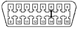
OBDII Connector
5. Reinstall the two grey pin retainers.
6. Locate the green “Star” connector above the parking brake. For 2018 plug the harness into any empty space, for 2019-2022 plug the harness into the fifth position from the left at the bottom.
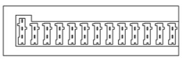
2018 Star Connector

2019-2022 Star connector
7. Cover & insulate the pins you removed from the OBDII connector.
8. Reinstall the OBDII connector into the factory location.
This cable is meant to be installed and left in the vehicle, NOT intended to be uninstalled and re-used. Once installed, the OBDII will still function normally.
The Cummins Bypass Cable (also known as the Security Gateway Module Bypass cable) can be used in the following scenarios and with multiple platforms: flashing a tune, changing the tire size, adding an aftermarket remote start, using a Snap-on or other OBDII scanner, or adding AMP Steps
Huge THANK YOU to Kyle Ensley at X-Ploit Diesel Performance for letting us use his original instructions for the 2018 as well as to Jarid Vollmer at Breakout Tuning for their assistance in designing this cable.
Part Number: FT2018-2022BypassCummins